Power Transformers 1
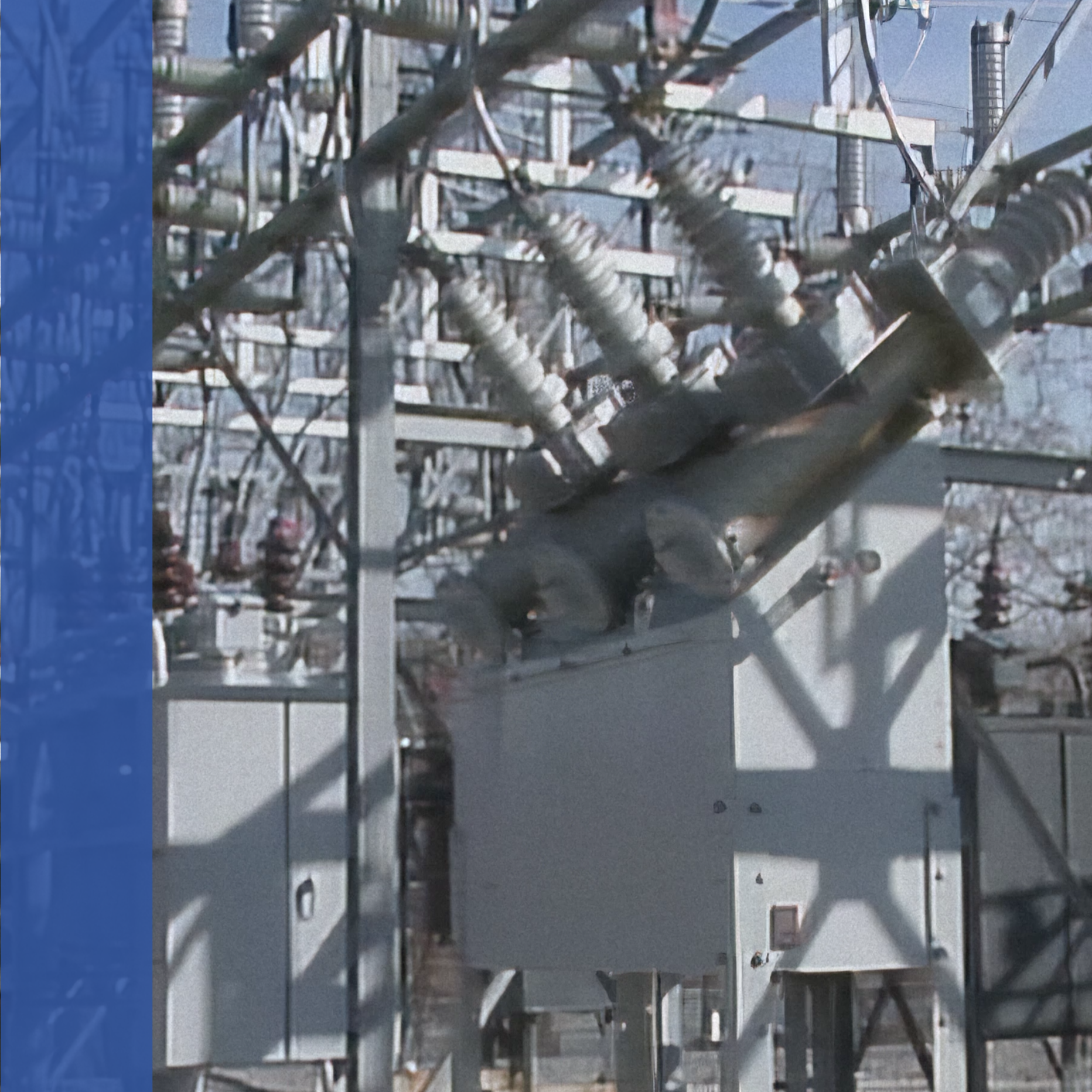
This course describes how power transformers work and introduces some of the more common types of power transformers found in substations and switchyards. This course also demonstrates how to recognize and identify specific classes of power transformers by their cooling systems and discusses how cooling systems work.

Power Transformers 2
This course demonstrates how to recognize and identify specific classes of power transformers by their sealing systems and discusses how these sealing systems work.

Circuit Breakers 1
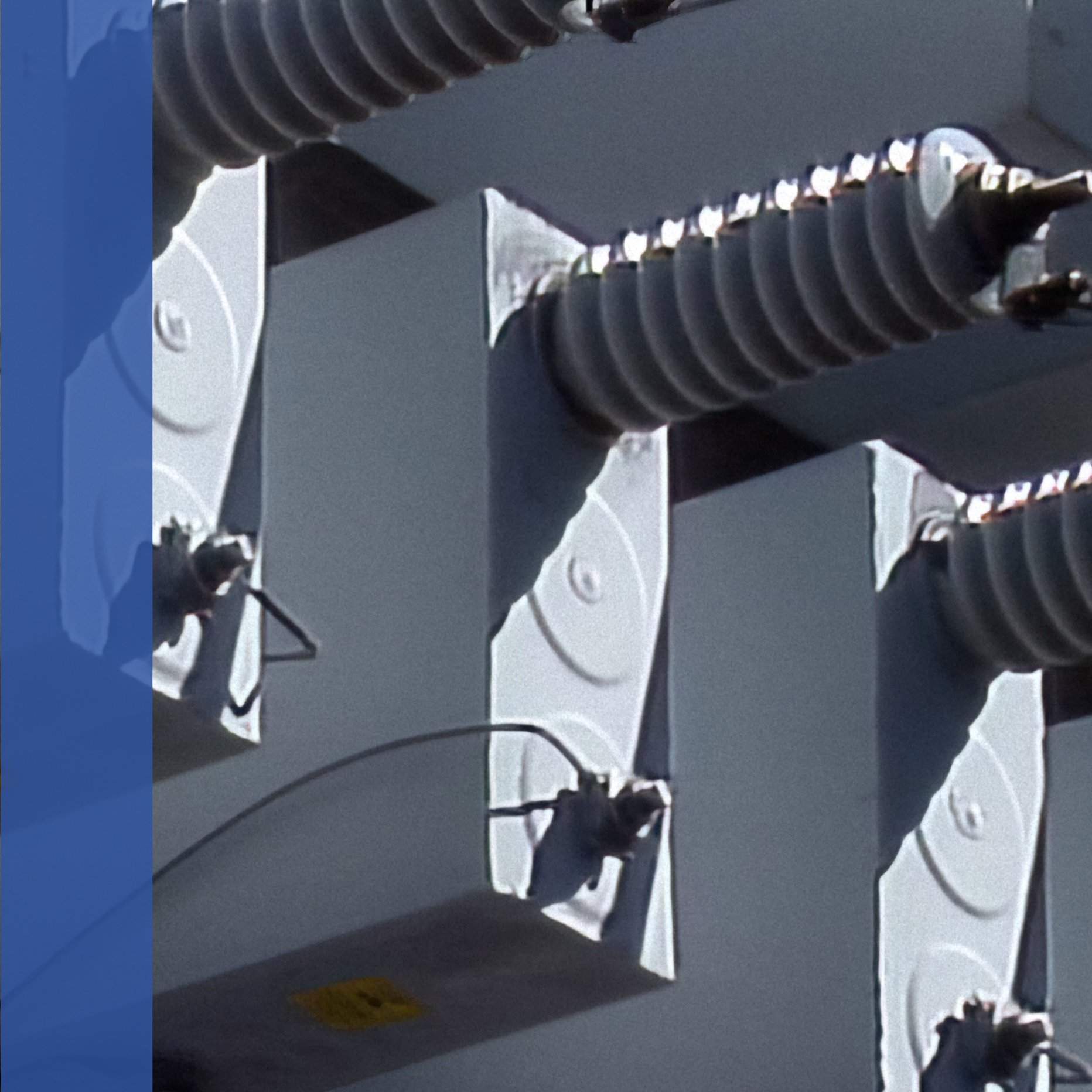
Part one of this course provides the trainee with an overview of circuit breakers and their operating principles. It also introduces the student to the fundamental concepts of arc extinguishing and circuit interruption. At the conclusion of this course, students should be able to describe the main functions of circuit breakers and identify them by their classification. In addition, they should be able to identify air-magnetic, air-blast, oil, and vacuum circuit breakers, and briefly describe how each one operates.

Circuit Breakers 2
This training program is designed to provide the student with basic information about circuit breakers that are used in substations and switchyards. The course shows how arcs are extinguished in gas-blast and gas-puffer breakers, and covers four types of breaker operating mechanisms: solenoid, motor/spring, pneumatic, and hydraulic.

Voltage Regulators 1
Utilities are required to provide power to their customers within a specific range of voltages. Voltages that are outside of that range may damage equipment or cause it to operate inefficiently. One method of maintaining voltage within a specified range is by using voltage regulators. This program discusses the operation and control of substation voltage regulators.

Voltage Regulators 2
This program describes the general procedures for performing voltage regulator field inspections and control checks. The program also describes how to remove a voltage regulator from service and how to put a new or replacement regulator into service.

Capacitors and Reactors
Conditions exist in any transmission and distribution system that result in power losses in the systems and equipment that deliver power and in the systems and equipment that use power. In order to compensate for these power losses, utilities often use devices such as capacitor banks and shunt reactors.

Relays 1
When a fault occurs in a transmission and distribution (T&D) system, current increases and voltage decreases. The increased current causes excessive heating, which, depending on where the fault occurs, can result in a fire or an explosion. If the fault is not quickly isolated, it can damage that may result in loss of service.
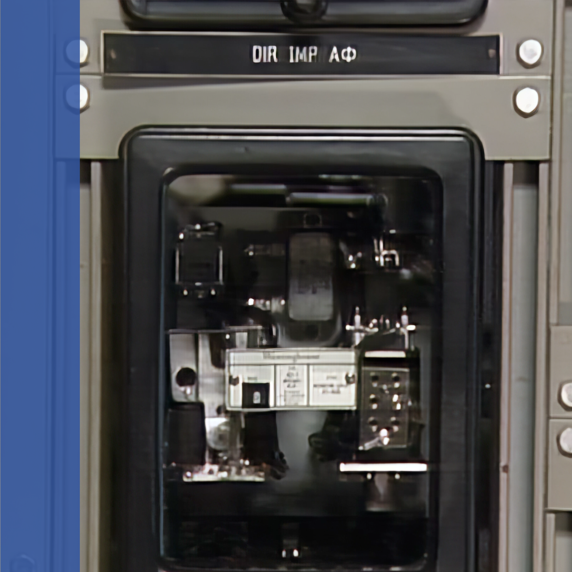
T&D systems use various types of control systems to detect and isolate faults with minimum disturbance. A key component of all of these control systems is the protective relay.

Relays 2
An electric power system includes generators, power transformers, transmission lines, switchgear, distribution circuits, and residential and business customer equipment. At any time, severe weather, accidents, or other factors may cause part of the system to fail. If the system is not properly protected, a failure can result in personal injuries and extensive equipment damage. One of the keys to protecting equipment and personnel from failures is the use protective relays.

Control Equipment
Disturbances and failures in a transmission and distribution (T&D) system can interrupt customer service and damage system equipment. Control equipment is the general name given to devices designed to minimize the effects of disturbances and failures. Control equipment helps to limit the number of customers affected by a given disturbance, as well as limit damage to the T&D system.

High Voltage Terminations
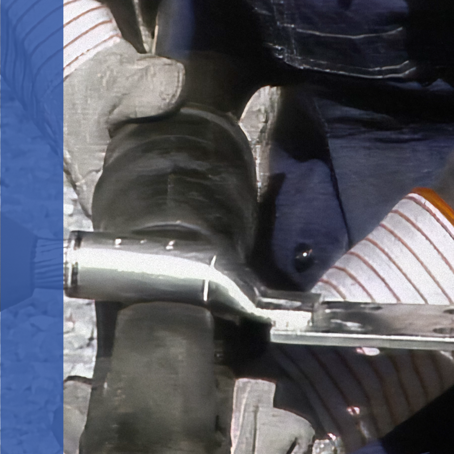
High-voltage cables are manufactured to exact specifications so that they can withstand a variety of mechanical and electrical stresses. When a high-voltage cable is terminated for a connection to a circuit or equipment in a substation or switchyard, the termination must also be made to exact specifications. If this is not done, the termination could become a weak point in the circuit.
